
 Profil NGI
 Výrobná základňa
 Služba sa
 Certifikáty


 Napájací zdroj servera AI
 Rada na ochranu BMS/batérie
 Elektronika 3C
 Automobilová elektronika
 Výroba čistej energie
 Ukladanie energie
 Polovodič / IC
 Po-predajný servis
 List
List Product Video
 Používateľská príručka
 Komunikačný protokol
 Softvér a ovládač
 Využitie
 Často kladené otázky
 použitie
 New príchodu
 Veľtrh
 EN
EN
 CN
CN AR
AR FR
FR IT
IT JA
JA KO
KO PT
PT RU
RU ES
ES TR
TR
Aplikácia ultrarýchlych elektronických záťaží pri testovaní doby odozvy prúdových senzorov
Current sensors are detection devices that use magnetic materials to sense the measured current and convert it into a standardized output according to a specific law (typically a linear relationship). Currently, electromagnetic sensors are widely used in automotive manufacturing, renewable energy generation, military aerospace, rail transportation, and other fields.
Doba odozvy is one of the critical performance indicators for sensors. It refers to the time difference between the output signal (secondary current, Is) and the input signal (primary current, Ip) during the rise phase—i.e., the delay between the output signal's rise time and the actual signal's rise. This parameter is particularly important for current sensors. Therefore, manufacturers and third-party testing institutions include response time testing in both type tests and routine tests.
Požiadavky na testovanie
Taking the standard TB/T 2763-2009 (Current and Voltage Sensors for Railway Vehicles) as an example, for closed-loop Hall current sensors, the standard specifies that the response time must meet the following thresholds: 1 µs, 3 µs, 15 µs, 20 µs, 50 µs, 100 µs.
Since the response time of current sensors is typically in the microsecond (µs) range, the testing equipment must have rapid current output capabilities. The test principle is illustrated below:
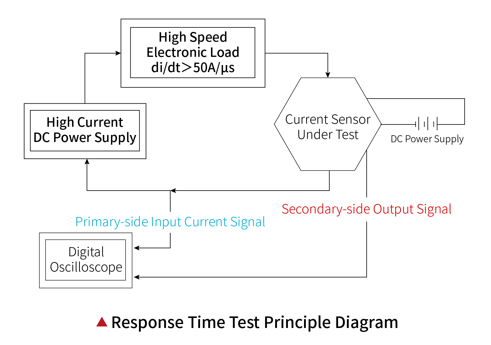
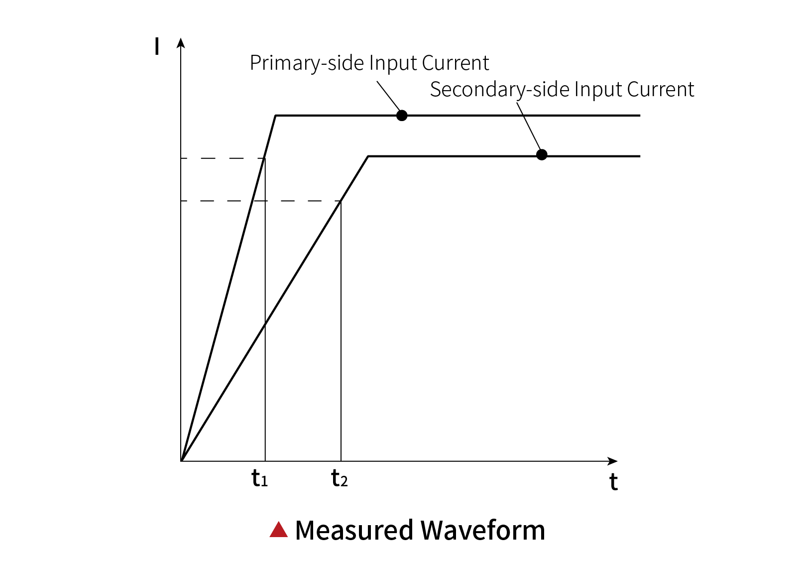
A high-speed signal source, zložený z high-current DC power supply a high-speed electronic load, inputs a signal with an amplitude equal to the sensor's rated current value to the device under test (DUT). The signal's rise slope must satisfy di/dt > 50 A/µs, and the amplitude must remain stable after reaching the rated value (see figure below).
Doba odozvy is measured as the time difference (t2 - t1) between the moments when the output signal and the input signal reach 90% of their amplitudes, as recorded by an oscilloscope. The oscilloscope must have duálne kanály, and its timebase accuracy should be no less than ± 5% to ensure precise waveform measurement.
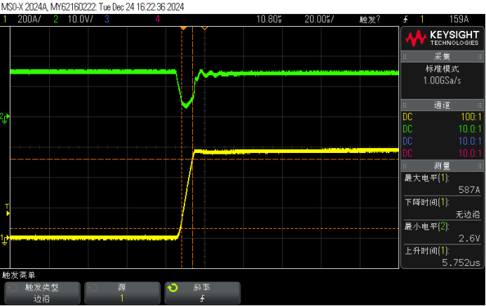
Actual Test Waveform
Séria N67000 of high-speed programmable DC electronic loads achieves ultra-fast current loading through optimized component selection and system loop design.The current rise slope reaches 100 A/µs at 580A, meeting the high-standard testing requirements for current sensor R&D and third-party certification.
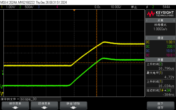
The measured response time of a channel in a three-phase current sensor of a well-known brand in the industry is as follows (387ns):
Séria N67000 je high-reliability, high-precision, and multifunctional high-speed programmable DC electronic load. It offers three power specifications: 600W, 1200W a 1800W, S 1.8kW power density in a standard 19-inch 2U chassis. Podporuje to master-slave parallel control for power expansion.
1. Ultra-High-Speed Current Loading: 60 A/µs
Single-unit current loading speed: 60 A/µs
Multi-unit parallel loading slope: >100 A/µs
Ideálne na testovanie current sensors, AI chips, and high-speed switching power supplies.
2. Full-Parameter Three-Range Measurement: V/I/R/W
Podporuje constant voltage (CV), constant current (CC), constant resistance (CR), and constant power (CP) režimy.
zaisťuje high-precision measurements across a wide range (1%–100%), vhodné pre current sensor accuracy and linearity testing.
3. Ultra-Low Operating Voltage: 0.7V @ 360A
The N67000 Series can operate at 0.7V under a 360A load, making it ideal for testing scenarios such as AI server power supplies and advanced CPU core power transient response analysis.
This capability allows engineers to evaluate chip performance under rapid load changes by observing voltage transients.